Bridge Rectifier: Definition, Circuit, and Applications
2026-05-04
115
Catalog
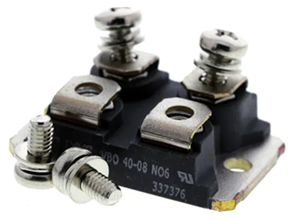
Figure 1. Bridge Rectifier Module
What Is a Bridge Rectifier?
A bridge rectifier is a simple electronic circuit used to convert alternating current (AC) into direct current (DC) using four diodes arranged in a bridge layout. Most electronic devices cannot use AC directly, so this circuit is commonly found in power supplies, chargers, and many everyday electronics. It works through full-wave rectification, which means it uses both halves of the AC signal to produce output, making it more efficient than simpler rectifiers.
When an AC voltage is applied, the polarity of the signal keeps changing between positive and negative. During the positive half cycle, two of the diodes become forward-biased and allow current to pass, while the other two block it. This creates a path where current flows through the load in one direction. When the AC input switches to the negative half cycle, the conducting diodes turn off and the other two diodes turn on. Even though the input polarity has reversed, the circuit is designed so that the current still flows through the load in the same direction. As of this switching action, the output never reverses, and both halves of the AC waveform are used.
The result is a pulsating DC output, which means the voltage rises and falls but does not change direction. This output is more efficient and has less energy loss compared to half-wave rectifiers. However, it is not perfectly smooth, so a filter capacitor is added to reduce ripple and make the DC output more stable. One advantage of a bridge rectifier is that it does not need a center-tapped transformer, which simplifies the design and reduces cost.
What Happens During the Positive Half Cycle
During the positive half cycle of a bridge rectifier, the AC input makes one terminal of the transformer (point A) positive and the other terminal (point B) negative. In this condition, diodes D1 and D2 become forward-biased, allowing current to flow, while diodes D3 and D4 are reverse-biased and block current. The current flows from the positive terminal A, passes through diode D1, then through the load resistor (RL), and returns to the negative terminal B through diode D2.
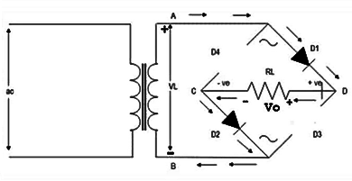
Figure 2. Bridge Rectifier Positive Half Cycle
As of this diode arrangement, the current flows through the load in only one direction, even though the input is alternating. The non-conducting diodes (D3 and D4) prevent current from flowing in the opposite direction. This ensures that the voltage across the load remains positive during this half cycle. As a result, the bridge rectifier produces part of a pulsating DC output, efficiently using the energy from the positive half of the AC waveform.
What Happens During the Negative Half Cycle
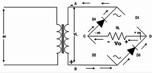
Figure 3. Bridge Rectifier Negative Half Cycle
During the negative half cycle, the polarity of the AC input reverses, so point B becomes positive (+) and point A becomes negative (−). This change causes a different pair of diodes to conduct: D3 and D4 turn ON (forward-biased), while D1 and D2 turn OFF (reverse-biased). The current flows from B → D3 → through the load (RL) → D4 → back to A. Even though the input voltage has flipped, the circuit automatically redirects the current so that it passes through the load in the same direction as before. This maintains a positive output voltage across RL, contributing to the continuous pulsating DC output of the bridge rectifier.
Bridge Rectifier Circuit Diagram
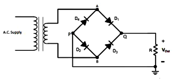
Figure 4. Bridge Rectifier Circuit Diagram
Bridge rectifier circuit consisting of four diodes (D1–D4) arranged in a bridge configuration. An AC supply is applied through a transformer, and the rectifier converts it into a DC output across the load resistor (R). The diodes control the direction of current flow, ensuring that the output voltage (Vout) remains in a single direction. This setup forms the basic structure used in full-wave rectification.
Why Bridge Rectifiers Don’t Need a Center Tap
A bridge rectifier does not need a center-tapped transformer because its four-diode configuration automatically handles both halves of the AC input. In traditional full-wave rectifiers that use a center tap, the transformer splits the AC signal into two equal halves so each half cycle can be processed separately. However, a bridge rectifier achieves the same result without splitting the transformer winding.
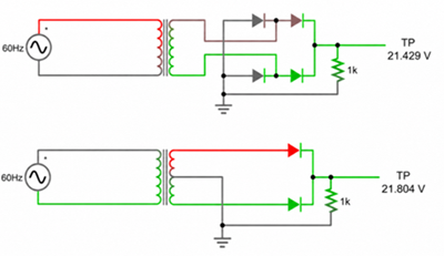
Figure 5. Bridge Rectifier vs Center-Tapped Rectifier
Instead of relying on a center tap, the bridge rectifier uses two pairs of diodes that conduct alternately. During one half cycle, one pair of diodes directs current through the load, and during the next half cycle, the other pair takes over. In both cases, the current flows through the load in the same direction, ensuring full-wave rectification.
This design eliminates the need for a center-tapped transformer, which simplifies the circuit and reduces cost. It also allows the transformer to use the entire secondary winding during both half cycles, improving efficiency and making better use of the available voltage.
Output Waveform and Performance of a Bridge Rectifier
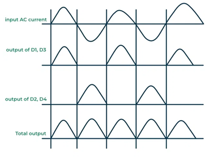
Figure 6. Bridge Rectifier Output Waveform
The output waveform of a bridge rectifier is a full-wave pulsating DC signal. This means the voltage no longer swings into the negative side like the original AC input. Instead, both the positive and negative half cycles are redirected into the same direction, creating a series of positive pulses across the load. The output is not perfectly smooth, but it is more useful than raw AC as the current flows in one direction.
Compared with a half-wave rectifier, a bridge rectifier performs better since it uses the entire AC waveform, not just one half of it. This gives a higher average DC output and supplies power to the load more often. For example, with a 50 Hz AC input, the output ripple frequency becomes 100 Hz. With a 60 Hz input, it becomes 120 Hz. As the ripple occurs more frequently, it is easier to reduce using a filter capacitor or other smoothing circuit.
In actual circuit performance, a bridge rectifier is efficient, ideal, and widely used in power supplies. However, the output is still pulsating DC, not pure DC, so filtering is required when a steadier voltage is required. Also, current flows through two diodes during each half cycle, which creates a small voltage drop. Even with this loss, bridge rectifiers remain a best choice since they provide good DC conversion, simple construction, and stable performance for many electronic applications.
Single-Phase vs Three-Phase Bridge Rectifier
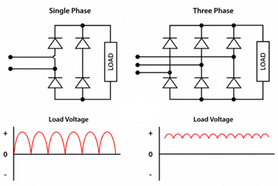
Figure 7. Single-Phase vs Three-Phase Bridge Rectifier Output
|
Parameter |
Single-Phase
Bridge Rectifier |
Three-Phase
Bridge Rectifier |
|
AC input source |
Single-phase AC |
Three-phase AC |
|
Number of diodes |
4 diodes |
6 diodes |
|
Output waveform |
Pulsating DC with
more ripple |
Smoother DC with
lower ripple |
|
Power level |
Low to medium power |
Medium to high power |
|
Circuit complexity |
Simpler |
More complex |
|
Cost |
Lower |
Higher |
|
Common Applications |
Adapters, chargers,
small power supplies, control circuits |
Industrial drives,
welding machines, motor systems, high-power chargers |
|
Best for |
Simple AC-to-DC
conversion |
Stable DC output for
heavy loads |
Bridge Rectifier vs Half-Wave Rectifier
|
Parameter |
Bridge
Rectifier |
Half-Wave
Rectifier |
|
Number of diodes |
4 |
1 |
|
AC waveform used |
Uses both positive
and negative half cycles |
Uses only one half
cycle |
|
Output type |
Full-wave pulsating
DC |
Half-wave pulsating
DC |
|
Output smoothness |
Smoother, with less
ripple |
Rougher, with more
ripple |
|
Ripple frequency |
Double the input
frequency |
Same as input
frequency |
|
Average DC output |
Higher |
Lower |
|
Efficiency |
Better |
Lower |
|
Transformer
requirement |
Does not need a
center tap |
Does not need a
center tap |
|
Circuit complexity |
More complex than
half-wave |
Very simple |
|
Common uses |
Power supplies,
chargers, adapters, electronic circuits |
Simple signal
detection, low-cost basic circuits, small experiments |
|
Best for |
Reliable AC-to-DC
conversion |
Very simple and
low-power applications |
Common Applications of a Bridge Rectifier
Phone chargers - Converts AC from the wall outlet into DC so a phone can charge safely.
Power adapters - Used in laptop adapters, router adapters, and small device adapters to create DC output.
LED bulbs - Helps change AC into DC as LEDs need DC current to light properly.
LED drivers - Provides the first DC conversion stage before the driver controls LED current.
Battery chargers - Converts AC into DC before the charging circuit sends power to the battery.
Power tool chargers - Used in chargers for drills, grinders, and other rechargeable tools.
Audio amplifiers - Converts AC into DC to power amplifier circuits.
Speaker systems - Used in powered speakers that need DC voltage inside the circuit.
TV power supplies - Helps convert AC wall power into DC for internal electronic boards.
Computer power supplies - Used in the input stage to convert AC into DC before further power regulation.
Routers and modems - Found in adapters that supply stable DC power to network devices.
Microwave oven control boards - Provides DC power for the low-voltage control circuit.
Washing machine control boards - Converts AC into DC for electronic control systems.
Welding machines - Used in high-power circuits that need strong DC output.
Automotive alternators - Converts AC from the alternator into DC to charge the car battery.
Emergency lights - Helps charge the battery and power the lighting circuit.
Solar inverter systems - Used in some power conversion stages where electricity must be rectified and controlled.
How to Choose the Right Bridge Rectifier for Your Application
Choosing the right bridge rectifier means checking whether it can safely handle your circuit’s voltage, current, heat, and working conditions. The goal is to choose a part that can convert AC to DC reliably without overheating or failing early.
Check the input voltage rating - Choose a bridge rectifier with a voltage rating higher than the AC voltage in your circuit. This helps protect the rectifier from voltage spikes and reverse voltage stress.
Correct current rating - The rectifier must handle the current required by the load. For example, a small charger may only need a low-current rectifier, while a motor drive or industrial power supply needs a much higher current rating.
Consider the diode voltage drop - In a bridge rectifier, current usually passes through two diodes at a time. This creates a small voltage drop, which can reduce the final DC output. This is required in low-voltage circuits where every volt matters.
Check heat dissipation - Bridge rectifiers can get hot during operation, especially at higher current levels. For high-power circuits, choose a rectifier with good thermal performance or use a heat sink.
Match the package type - Bridge rectifiers come in different packages, such as small PCB-mounted types and larger metal-case modules. Choose one that fits your circuit board, space, and power level.
Decide between single-phase and three-phase - Use a single-phase bridge rectifier for common low- to medium-power AC supplies. Use a three-phase bridge rectifier for industrial machines, motor drives, and high-power systems.
Look at the application environment - If the rectifier will be used in hot, dusty, vibrating, or industrial conditions, choose a more durable part with higher safety margins.
Why Bridge Rectifiers Overheat
A bridge rectifier overheats when it produces more heat than it can release safely. During operation, current passes through two diodes at the same time, and each diode has a small voltage drop. This voltage drop creates power loss, and that lost power turns into heat. The higher the load current, the more heat the rectifier produces.
Overheating can also happen when the rectifier is underrated for the circuit. For example, if the load needs more current than the rectifier can handle, the part will run hot and may fail early. Poor cooling is another cause, especially when the rectifier is placed in a tight space, has no airflow, or is used without a heat sink in a high-power circuit.
Other possible causes include wrong wiring, short circuits, high input voltage, damaged diodes, or large filter capacitors that create a high startup surge current. To prevent overheating, choose a bridge rectifier with enough voltage and current margin, check the actual load current, provide proper ventilation, and use a heat sink when needed.
δοκιμή λειτουργίας.Τα υψηλότερα οικονομικά αποδοτικά προϊόντα και η καλύτερη υπηρεσία είναι η αιώνια δέσμευσή μας.
Καυτό άρθρο
- LM358 Διπλός λειτουργικός ενισχυτής Περιεκτικός οδηγός: Pinouts, διαγράμματα κυκλώματος, ισοδύναμα, χρήσιμα παραδείγματα
- Είναι εναλλάξιμα τα CR2032 και CR2016;
- Κατανόηση των διαφορών ESP32 και ESP32-S3 Τεχνική και ανάλυση απόδοσης
- Επιλέγοντας τη σωστή μπαταρία: Οδηγός για τα AG4, LR626, LR66, 177/376/377, SR626 και SR626SW ισοδύναμα
- Βασικά στοιχεία τρανζίστορ BC547: Pinout, κυκλώματα εφαρμογής, εναλλακτικά/συμπληρωματικά μοντέλα
- NPN εναντίον PNP: Ποια είναι η διαφορά;
- ESP32 VS STM32: Ποιος μικροελεγκτής είναι καλύτερος για εσάς;
- Τι είναι το MOSFET και πώς λειτουργεί;
- Ηλεκτρικό ρελέ Basic: Λειτουργία εργασίας, τύποι και χρήσεις
- Τρανζίστορ PNP: δομή, αρχή εργασίας και εφαρμογή
 Op-Amp vs Differential vs Instrumentation Amplifier Explained
Συχνές ερωτήσεις [FAQ]
1. Why does a bridge rectifier need a filter capacitor?
A filter capacitor reduces ripple in the rectified output. It stores energy when the voltage rises and releases energy when the voltage drops, making the DC output smoother.
2. What happens if one diode fails in a bridge rectifier?
If one diode fails, the output may become weak, unstable, or completely lost. It can also cause high ripple, overheating, or short-circuit problems depending on how the diode fails.
3. Can I use four separate diodes instead of a bridge rectifier module?
Yes. Four separate diodes can be connected to form a bridge rectifier. However, a ready-made bridge rectifier module is usually easier to install, more compact, and better for clean PCB design.
4. Can a bridge rectifier work without a capacitor?
Yes. It can convert AC into pulsating DC without a capacitor. However, the output will rise and fall strongly, so it may not be suitable for circuits that need steady DC voltage.
5. How do you test a bridge rectifier with a multimeter?
Use the diode test mode on the multimeter. Each diode path should conduct in one direction and block in the opposite direction. If it conducts both ways or blocks both ways, the rectifier may be damaged.
6. Why is my bridge rectifier output voltage low?
Low output voltage may be caused by diode voltage drop, an overloaded circuit, weak transformer output, wrong rectifier rating, damaged diodes, or excessive ripple under load.
7. Which is better, bridge rectifier or center-tapped rectifier?
A bridge rectifier is better for general use since it does not need a center-tapped transformer and uses the full secondary winding. A center-tapped rectifier may have lower diode voltage drop but needs a special transformer.
Καυτός αριθμός εξαρτήματος
 ESD35C104K4T2A-24
 12101A222JAT2A
 06031A1R3CAT2A
 CC1206KKX7R6BB155
 T491B685M010AT
 F971A336KCC
 TAP154K035CRW
 TPSB336K006R0350
 98424-G52-08ALF
 AOD4454
- U211B-MFP
- ERJ-3EKF2741V
- ATMEGA1284-MUR
- MC13892DJVLR2
- OPB840W51Z
- FGA6065ADF
- T491C106M025AT4053
- SPC5604SF2VLQ6R
- LM2674M-3.3/NOPB
- ADUM2250ARIZ
- CY74FCT646ATQCT
- MC14071BDR2G
- ADS1240E/1K
- MC74LCX573DTR2G
- TPS65050RSMT
- LPC660AIM
- LT1480IS8
- AT91SAM9261-CU
- BA3575FS
- CA0324M96
- HD6417092TE20
- LE79534JC
- LTC2951CTS8-1
- M27C2001-80XF1
- M306N4FGTGP
- PS2801C-4
- TLC27L4CN5R
- TMP432AGKR
- TW8803-AARA
- UF1050BU
- CSP1040A2-V11-D
- GW3887AIK-TK
- HTP25NP
- SN75ALS180
- SE-BE4210-P01
- TSUM5PFHJ-LF-4
- ADW80031XSTZ
- HC4P5504B-5X96
- LM61495QRPHRQ1